
Case Study: Problems & Solutions for Complex Rock HDD Directional Drilling
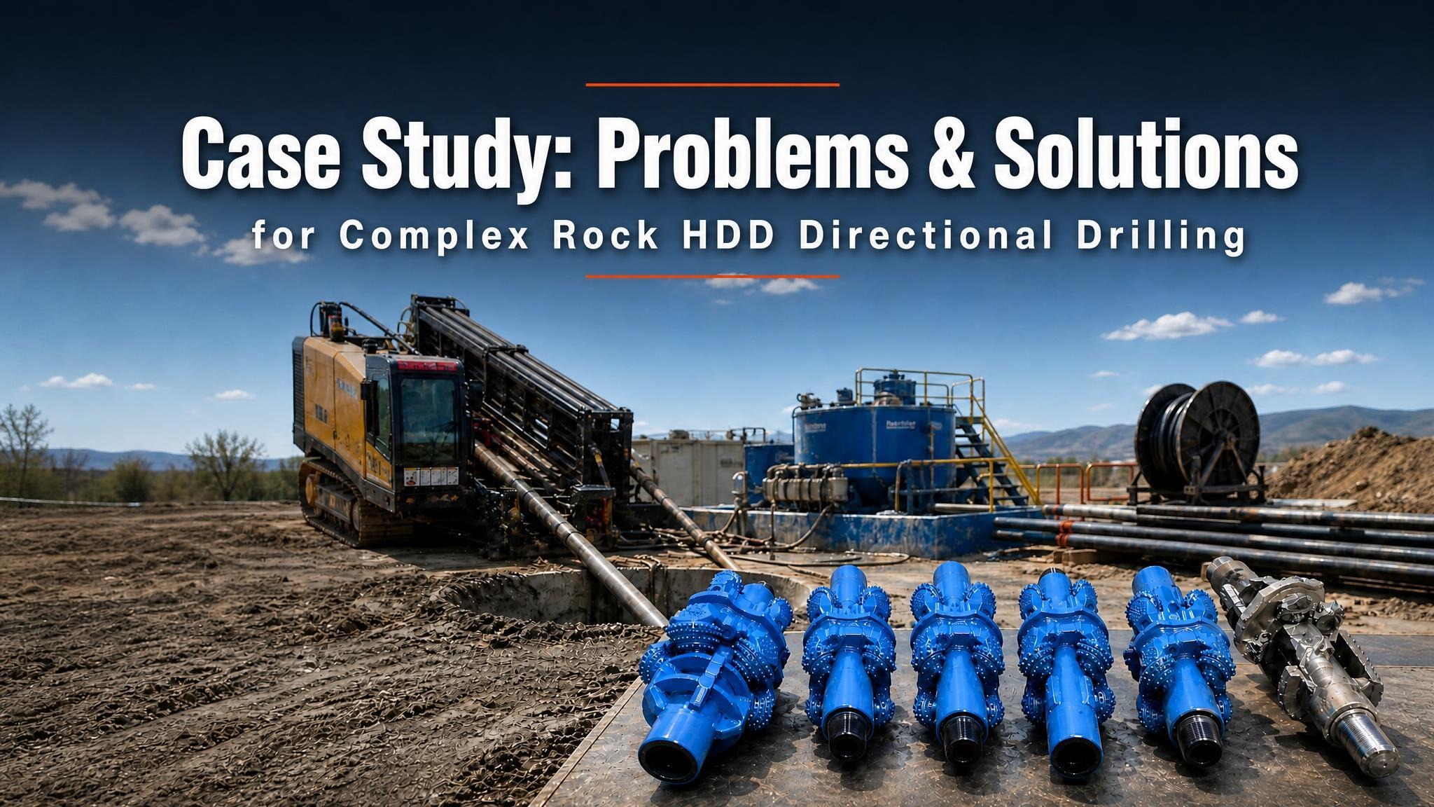
Case Study: Problems & Solutions for Complex Rock HDD Directional Drilling
I.Project Overview
1. Natural Conditions
The crossing location of Chengxi Avenue II is in Fujian Province. On the west side of the crossing section are road green belt and Chengxi Avenue, and the site is relatively narrow. On the east side are residential houses, the site conditions are general, and transportation is convenient. Horizontal directional drilling (HDD) is adopted for the crossing: one Φ457 mm main pipe and one Φ114 mm optical cable casing. The actual crossing length is 175 m, including 115 m in rock.
2. Geological Conditions
According to differences in geological age, origin, lithology, and physical and mechanical properties of the soil, the crossing site is divided into 6 engineering geological layers: ① fill, ② medium-coarse sand, ②1 mucky silty clay, ③ silty clay, ④ sandy strongly weathered granite, ⑤ blocky strongly weathered granite, and ⑥ moderately to slightly weathered granite.
According to the strata exposed on site, the soil layers are fill, medium-coarse sand, mucky silty clay, and strongly to slightly weathered granite. It is recommended that the pipeline be mainly placed in layer ④ sandy strongly weathered granite, and that the crossing be carried out by HDD.
II. Project Characteristics and Technical Difficulties
The original design entry point was in the open area under the green belt. Due to local relations and topography, both the entry and exit points were moved to the green belt on the east side of Chengxi Avenue. The green belt is 8 m wide. Beneath it, a group of six optical cable casings and one Φ1000 V-PVC sewage pipe have already been laid. They intersect both the entry/exit points and the crossing axis, and a sewage sedimentation tank is located on the crossing centerline. This increases construction risk during crossing.
The Huinü Canal in Hui'an County passes under Chengxi Avenue and is perpendicular to the crossing centerline. During construction of the Huinü Canal, blasting was used on the hillside to the right of the crossing centerline, and backfill was used on the left side. The underground conditions are very complex.
The crossing location is at a bend of Chengxi Avenue. Behind both the entry and exit points are the road surface of Chengxi Avenue. Limited by length, the crossing curve has no horizontal section. It must be ensured that each drill rod reaches the design angle; otherwise, the bit cannot exit at the required position.
The crossing section contains a 115 m long rock layer, mainly moderately to slightly weathered granite. A downhole motor must be used, which causes a steering signal lag of about 10 m and increases steering difficulty.
The pipeline to be pulled back on the exit side was prefabricated along the green belt of Chengxi Avenue and has a large angle with the crossing centerline, making pullback construction difficult.
There is a residential house 5 m to the right of the centerline. Because the rock is hard and some strata are backfill, reaming may cause large vibration and adversely affect the house.
III. Main Technical Measures
3.1 Pilot Hole Construction
1. Pilot Hole Construction Measures
(1) To avoid the group of six optical cable casings, excavate the ground 2–8 m ahead of the entry point, expose the optical cable casings, and take protection measures.
(2) Ahead of the entry point, excavate at the intersections between the crossing path and the Φ1000 V-PVC sewage pipe and sewage sedimentation well, measure the exact elevation difference of their bottoms relative to the entry point, and calculate the relative position between the crossing path and the sewage pipe and sewage sedimentation well according to the design curve. Calculation showed that the crossing path conflicted with underground obstacles. With design approval, the entry point was moved backward to increase the distance between the entry point and underground obstacles and ensure that the obstacles are avoided.
(3) After accurately locating the sewage pipe and its depth on the exit side, calculation showed that, limited by the site, the original design path could not avoid the sewage pipe. With design approval, the exit point was shifted 3 m to the right to avoid the sewage pipe on the exit side.
(4) Design a reasonable crossing curve according to underground obstacles to ensure that the crossing path avoids underground obstacles.
(5) Use the Sharewell MGS steering system for pilot hole construction.
(6) Set up an artificial magnetic field along the entire route to ensure steering accuracy. Mark the crossing centerline and underground obstacle positions on the ground, and compare the accurate bit position measured by the artificial magnetic field with the underground obstacle positions to ensure that the bit is within a safe range.
(7) During pilot hole construction, use a BHA of 9-1/2″ tricone bit + 172 downhole motor + 7″ non-magnetic drill collar for rock drilling.
(8) During drilling, keep records for each drill rod, including penetration rate, the length pushed during angle adjustment, time used, and angle changes, so as to judge formation changes and summarize steering rules in different formations.
(9) Because the downhole motor causes a signal lag of about 10 m, it is necessary to judge, based on the drilling condition of the previous drill rod and the angle change of the current drill rod, the drill rod length required to adjust a certain angle in the same formation, and then determine the drilling method for the next drill rod.
(10) During drilling, measure each drill rod with the artificial magnetic field, and adjust the reference azimuth according to the deviation to ensure that the pilot hole deviation is within the allowable range. Correct deviations promptly to avoid excessive deviation that cannot be corrected.
(11) Set up mud recycling and purification systems at both entry and exit points to recycle the returning mud.
2. Problems Encountered and Solutions
When drilling reached 70 m, the bit was below the Huinü Canal, and the bit angle suddenly became uncontrollable. The angle increase per single drill rod reached 4.4° (according to the pipeline radius of curvature, it should not exceed 0.8°). Based on the drilling and geological conditions, it was analyzed that there may be a soft-hard formation interface at a small angle to the drilling direction. When the bit reached this location, it advanced along the surface of the hard formation, causing the inclination to become uncontrollable.
After repeated push-pull hole conditioning, no effect was achieved. The bit was pulled back into the soil layer, and pilot drilling was restarted after changing the direction and depth. At 80 m, the angle could not be increased. If drilling continued, the bit would not be able to exit at the planned position. Because there was no remaining crossing position at the entry side, the rig had to be moved to the exit point for pilot hole construction.
During re-drilling, the crossing centerline and crossing depth were properly adjusted to avoid the soft-hard formation interface as much as possible, and the bit finally exited successfully. However, at about 70 m from the entry point, a relatively large angle change still existed.
3.2 Reaming Construction
1. Reaming Construction Measures
(1) Determine the suitable reamer type and reaming stages according to the drilling and geological conditions.
(2) For the Φ457 pipeline, three stages of rock reamers were used: Φ450 mm, Φ600 mm, and Φ750 mm. During reaming, closely monitor changes in pullback force and torque, and strictly record the service time of the BHA to prevent accidents such as cone loss.
(3) In soft formations, properly increase the advance speed to prevent the reamer from sinking and forming a pear-shaped hole.
(4) When reaming in blocky strongly weathered granite, control the pull force and torque to prevent stuck pipe accidents and reduce the impact of vibration caused by large torque changes on the residential house.
(5) After reaming with each drill rod is completed, repeatedly push and pull to clean the hole and ensure good hole quality.
(6) After reaming is completed, carry out hole conditioning to ensure good hole quality and a smooth curve before pullback. The hole conditioning BHA is: Φ500 rock reamer (rear) + Φ450 rock reamer + Φ430 centralizer + Φ450 rock reamer + Φ600 rock reamer (front).
(7) Use different mud mixes and parameters for different formations. In rock layers, ensure cuttings-carrying capacity and sufficient flow rate. In soft layers, control the mud flow rate to prevent mud breakout.
(8) During reaming, recycle mud through the mud recycling and purification system, strengthen testing of mud properties, and adjust timely to ensure compliance with construction requirements.
2. Problems Encountered and Solutions
(1) When the Φ750 mm rock reamer reamed to 70 m from the entry point, there was basically no penetration. According to the pilot hole construction records, the angle change per single drill rod at this location was 3.8°. Analysis showed that the large angle change caused the centralizer ahead of the reamer to be blocked by the rock layer, and the reamer cones could not contact the rock for cutting.
A Φ600 mm rock reamer was added ahead of the reamer to replace the centralizer. The Φ600 mm rock reamer first conditioned the hole, and then the rear Φ750 mm rock reamer cut the rock. The Φ750 mm reaming construction was completed smoothly.
(2) During hole conditioning, there was no penetration at 70 m from the entry point. Analysis showed that this was still due to the large angle change, and the hole curve did not meet the radius of curvature.
The front Φ600 rock reamer was swapped with the rear Φ450 rock reamer. Using the rigidity of the BHA, the hole was conditioned step by step to meet the required radius of curvature, and the hole conditioning construction was finally completed.
(3) During hole conditioning, based on torque changes, it was considered that there was 100 mm–200 mm crushed rock in the hole, which might affect the pipeline during pullback.
A fishing barrel with an outer diameter of 650 mm was used to remove the crushed rock from the hole. After the larger crushed rock was cleaned out, pullback work was carried out.
3.3 Pullback Measures
Because the pipeline to be pulled back had a large angle with the crossing centerline, before pullback the pipeline was placed in the median green belt of Chengxi Avenue, and more than 50 m of pipeline near the entry point was adjusted to form a straight line with the crossing centerline. Pipeline placement should meet the pipeline radius of curvature.
Use a launch cradle to protect the pipeline anti-corrosion coating.
Place anchor blocks at the elastically laid sections of the pipeline to prevent lateral sliding during pullback.
During pullback, lifting equipment shall cooperate and adjust the pipeline at any time.
Pullback should be carried out continuously to prevent pullback failure caused by too long a stoppage.
IV. Conclusion
In short-distance rock HDD construction, control of the crossing curve, correction of the pilot hole, and cleaning of cuttings in the hole are key factors for successful pullback. Through this project, valuable experience has been accumulated in technical measures for rock crossing and methods for handling main problems, laying a solid foundation for future rock crossing construction.
Your email address will not be published. Required fields are marked with *


